How to replace the DE1 manifold
![]()
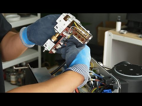
The “manifold” in the DE1 espresso machine is what guides water to various destinations, as well as measuring temperature and pressure.
In this video, we'll walk you through the entire process of replacing the manifold.
You'll need to do this:
- When there is leakage from a crack in the manifold.
- When one of the valves is not working properly.
- When the manifold board is malfunctioning.
This video is part of a series that we produce, helping people self-repair their Decent Espresso Machine.
In the early models of the DE1 (v1.0 and v1.1) repeated use (especially in a cafe) would cause “heat cycling” and could cause this part to crack and slightly leak. This was addressed both with design changes (such as removing bolts that tightly held the parts that were expanding/contracting) and changing to a material that has reinforcing fibers embedded in it.
The “mixing manifold” warranty was extended (at no cost to our customers) to five years (instead of the default two) as we felt it was our responsibility.
Tools Needed
- T10 Torx screwdriver
- PH2 Phillips screwdriver
- Angled & straight pointy tweezers
- 2mm, 2.5mm, or 3mm hex key (for older versions)
- Comfort grip gloves
- Thin, durable tool (for separating stuck parts)
- Nippers (for cable ties, if needed)
Step 1: Power Disconnection
For XL or XXL Models:
- Remove the back panel.
- Turn off the machine's back switch.
- Unplug the power cord.
For Pro and Plus Models:
- Turn off the machine's back switch.
- Unplug the power cord.
For Version 1.43 or Higher (Slide-Type Tablet Stand):
- Unplug the USB cable.
- Gently pull the tablet stand out.
For Version 1.3 to 1.42 (Screw-Type Tablet Stand):
- Unscrew the three screws holding the tablet stand.
- Remove the stand.
Step 2: Remove External Components
- Remove the drip tray and drip tray cover.
- Lift the lever on the back and slide out the water tank.
- Remove the portal filter and brew head handle.
Step 3: Remove the Main Cover
- Use a T10 screwdriver to remove the 8 screws on the main cover.
- Gently stretch the sides of the cover and lift it off.
Step 4: Remove the Chassis
- Check if the manifold screws are T10 Torx or PH2 Phillips.
- Remove the six screws securing the chassis.
- Remove the two screws above the pumps (use appropriate screwdriver).
- Use angled tweezers to remove the clip on the purple tube, then pull the tube out.
- Wear gloves and gently pull the silicon tube from the return valve.
Step 5: Disconnect Tubes from Manifold
- Remove three tubes at the front and three tubes on the Ox manifold.
- Remove the dark orange tube from the Mix manifold.
Step 6: Unplug Sensor Cables
Use tweezers based on connector visibility:
- Brown sensor (top): Straight tweezers
- Blue sensor: Angled tweezers
- Gray sensor: Angled tweezers
- Purple/orange sensor: Straight tweezers
- Black/dark blue sensor: Angled tweezers
Step 7: Remove Cables from Manifold Board
- 7-pin cable: Use fingernails to gently pull from the gap.
- Drain valve cable: Press the clip while pulling (wiggle if stuck).
- A-pin cable: Same as 7-pin removal.
- Valve power cable (last one): Press the clip while pulling (wiggle if needed).
Step 8: Lift Out the Manifold
- Once all cables/tubes are disconnected, lift the manifold out.
Step 9: Replace MixAux Manifold (If Needed)
(Skip if replacing full manifold.)
- Remove 2 or 4 screws from MixAux manifold bracket:
- Current version: T10 Torx
- Older versions: 2mm/2.5mm/3mm hex key
- Unplug sensor cables (white → yellow → green) using angled tweezers.
- Remove the clip from the yellow-green tube and pull it out.
- Pull MixAux manifold out (use a thin tool if stuck due to melted rubber pad).
- Remove O-rings using a T10 screwdriver (7 from MixAux, 3 from main, 1 from purple tube).
Step 10: Reassemble MixAux Manifold
- Place the rubber pad on the main manifold bracket (purple tube faces pressure sensor).
- Align Mix Aux manifold and insert first screw (finger-tighten, then halfway with T10).
- Insert second screw and fully tighten, then finish tightening the first.
- Plug in sensors (green → yellow → white).
- Install U-shaped tube with O-rings (insert gently with circular motion).
Step 11: Reinstall Manifold
- Plug in valve power cable (align 8 pins, push until click).
- Plug in A-pin cable (exposed side faces open connector).
- Plug in drain valve cable (push until click).
- Plug in 7-pin cable (exposed side faces open connector).
Step 12: Reconnect Tubes
- Use white O-rings first (brown if leaks occur).
- Insert tubes in this order:
- Ox manifold: Green → yellow → orange
- Mix manifold: Yellow-green → dark orange
- Front: Brown → blue → gray
Step 13: Final Reassembly
- Reinstall return valve silicon tube and purple tube.
- Secure the two screws above pumps (first halfway, align, then fully tighten).
- Run leakage tests (use “Forward Flush Multiply 5” profile).
Troubleshooting & Support
- If leaks occur, check O-rings and tube connections.
- For issues, contact tech support.
Done! Your manifold replacement is complete.
Updated 2025/05/08