In this video, we'll show you how to replace the P10 sensor.
If the metal temperature rises properly, but the app nonetheless displays WAIT forever, the P10 sensor may not be working properly. You will need to replace the sensor in that case.
This video is part of a series that we produce, helping our users self-repair their Decent Espresso Machine.
Only do this repair in consultation with Decent tech support
Doing otherwise might break your machine or void your warranty.
Chapters:
2.
00:09 Power Disconnection
3.
00:29 Remove External Components
4.
01:11 Remove the Main Cover
5.
01:33 Remove the Chassis
6.
02:03 Turn the machine upside down
7.
02:32 Remove the 5 screws on the group head support
8.
02:58 Turn the machine back into its upright position
9.
03:13 Lift the group head cover and insulation plate
10. 03:32 Remove the cable ties holding the wires
11. 03:57 Remove the sensor connector from the manifold board
12. 04:18 Loosen the sensor
13. 04:40 Install the new P10 sensor
14. 05:03 Connect the sensor cable
15. 05:24 Mount new cable ties
16. 06:25 Organize the insulation plates and cables
17. 06:39 Close the group head
18. 06:52 Re-install the side chassis
19. 07:16 Place a cloth and turn the machine upside down
20. 07:29 Mount the group head screws
21. 07:56 Contact us with questions
P10 Sensor Replacement Instructions
Tools Needed
T10 Torx screwdriver
PH2 Phillips Head Screwdriver
Angled pointy-tip tweezers
Adjustable Wrench
Nippers
2 x Cable tie
Cloth
Step 1: Power Disconnection
For DE1XL or DE1XXL Models:
1. Remove the back panel.
2. Turn off the machine's back switch.
3. Unplug the power cord.
For DE1PRO and DE1PLUS Models:
1. Turn off the machine's back switch.
2. Unplug the power cord.
Step 2: Remove External Components
For Version 1.43 or Higher (Slide-in Tablet Stand):
1. Unplug the USB cable.
2. Gently pull the tablet stand out.
For Version 1.3 to 1.42 (Screwed-in Tablet Stand):
1. Unscrew the 3 screws holding the tablet stand.
2. Remove the stand.
Then...
1. Remove the drip tray.
2. Remove the drip tray cover.
3. Lift the lever on the back of the machine.
4. Slide the water tank out and remove it.
5. Remove the portafilter.
6. Remove the group head handle.
Step 3: Remove the Main Cover
1. Use a T10 screwdriver to remove the 8 screws securing the main cover.
2. Gently stretch the sides of the cover outward.
3. Lift the cover off the machine.
Step 4: Remove the Chassis
1. Identify the screw type for the manifold (T10 Torx or PH2 Phillips).
2. Remove the 6 screws securing the chassis.
3. Remove the side screw of the boardroom lid (T10 or PH2).
4. Remove the lid
Step 5: Open the Group Head Cover
1. Place a soft cloth on the table.
2. Rotate the steam wand to a horizontal position.
3. Flip the machine upside down and place it gently on the cloth.
4. Use a T10 Torx screwdriver to remove the 5 screws located under the group head.
5. Use angled tweezers to pull the screws out after loosening them.
6. Flip the machine back to its upright position.
7. Lift the group head cover straight off.
8. Lift the bottom insulation plate to access the interior components.
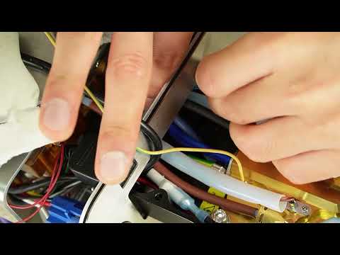
Step 6: Remove the cable ties
1. Cut the cable tie bundling the black and blue wires using nippers.
2. Cut the cable tie bundling the black and blue wires together with the black tube.
3. If any cut cable tie pieces fall down, pick them up with tweezers.
Step 7: Remove the sensor cable from the board
1. Use angled tweezers to remove the sensor from the manifold board.
2. Gently pull the sensor cable toward the group head.
3. If the connector gets stuck between the manifold and the chassis, adjust its angle and pull it out slowly.
Step 8: Detach the old sensor
1. Once the connector is out, use an adjustable wrench to loosen the sensor.
2. When it's loose, unscrew it with your fingers.
3. While unscrewing, rotate the cable together with the sensor head to avoid twisting it.
Step 9: Install the new P10 sensor
1. Place the new P10 sensor in position.
2. Screw it in with your fingers, rotating the cable together with the sensor head.
3. When it no longer turns by hand, use an adjustable wrench to tighten it slightly. Do not overtighten it—the bolt can break.
Step 10: Connect the cable
1. Insert the connector and cable through the chassis hole leading to the group head.
2. Route the connector back toward the manifold board.
3. Connect the cable to its port on the manifold board.
Step 11: Install new cable ties
1. Use a cable tie to bundle the black and blue wires.
2. Use another cable tie to bundle the black and blue wires together with the black tube.
Step 12: Close the Group Head
1. Tidy up the insulation plates and ensure all cables are properly positioned.
2. Ensure the ground cable is not pinched between any metal parts.
3. Slightly tilt the group head back.
4. Insert the rear tab of the chassis into the group head opening.
5. Gently close the group head.
Step 13: Install the Side Chassis
1. Install the side chassis.
2. Secure it using all six T10 or PH2 screws.
Step 14: Mount the Bottom Screws
1. Place a cloth on the table.
2. Use a thick enough cloth to support the group head evenly. If necessary, fold the cloth to increase its thickness.
3. Flip the machine upside down again.
4. Insert all 5 bottom screws.
5. Start with the top left or right screw for initial alignment.
6. Adjust the group head angle as needed for proper alignment.
7. Screw in the first 4 screws only halfway.
8. Fully tighten all 5 screws once they are aligned.
Step 15: Final Check
1. The repair and reassembly are complete.
2. If you have any questions or issues, please contact our support team.
#repair #howto #DIY #documentation